

Introduction: 5 PLC Programming Languages
Programmable Logic Controllers (PLCs) are indispensable tools in industrial automation, as they are used to control and monitor machinery and processes efficiently. Furthermore, PLC programming languages play a crucial role in this automation process because they determine precisely how the controller interacts with the machinery or devices it manages. In this article, we will, therefore, delve into the top 5 PLC programming languages that are widely used across the industry today, highlighting their features, applications, and benefits.
5 PLC Programming Languages
1. Ladder Logic (LAD):
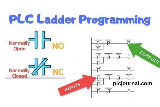
Ladder Logic, also known as LAD, is one of the most commonly used PLC programming languages. It derives its name from the ladder-like appearance of the programming diagrams. Moreover, Ladder Logic (LAD) mimics the behavior of electromechanical relays, which makes it particularly intuitive for electricians or technicians who are already familiar with traditional relay circuits. Additionally, the visual representation of circuits in Ladder Logic facilitates easy troubleshooting and modification, thereby enhancing efficiency and reducing the likelihood of errors during programming.
2. Structured Text (ST):
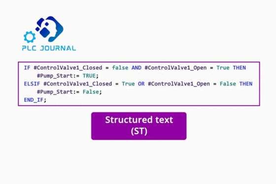
Structured Text (ST) is a high-level PLC programming language that closely resembles the syntax of the Pascal programming language. Furthermore, it offers a wide range of programming possibilities, making it particularly suitable for complex control algorithms and advanced mathematical operations. As a result, ST is primarily used for implementing sophisticated control strategies and performing precise calculations within PLC programs, thereby enhancing overall system functionality and flexibility. However, its usage requires a solid understanding of programming concepts.
3. Function Block Diagram (FBD):
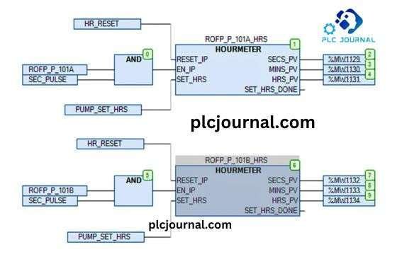
Function Block Diagram (FBD) is a graphical PLC programming language that uses interconnected function blocks to represent the control logic. Moreover, each block corresponds to a specific function, while the interconnections between blocks determine the sequence of operations. Consequently, FBD offers a versatile and modular approach to programming, which not only simplifies code reuse but also makes maintenance and troubleshooting more efficient. It is particularly useful for designing complex control systems involving multiple devices or machines.
4. Instruction List (IL):
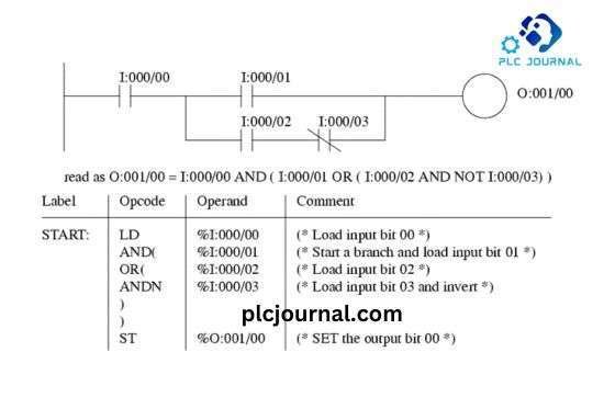
Instruction List (IL) is a low-level PLC programming language primarily used by experienced programmers. Furthermore, it closely resembles assembly language and, therefore, requires a solid understanding of the PLC’s instruction set. In addition, IL is both concise and efficient, making it especially suitable for time-critical applications where speed and precision are essential. However, due to its complexity, it is less commonly utilized compared to other languages.
5. Sequential Function Chart (SFC):
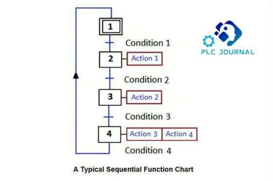
Sequential Function Chart (SFC) is a graphical PLC programming language designed to model complex control sequences. Moreover, it enables the representation of the sequential flow of operations through clearly defined steps, transitions, and actions, thereby making it easier to visualize, design, and manage intricate processes efficiently. SFC is particularly effective in applications where a machine or process undergoes sequential steps, such as batch processing. The visual representation facilitates the analysis and understanding of the control flow.
5 PLC Programming Languages
Which Top 5 PLC Programming Language is Best for PLC
Understanding PLC Programming Languages
PLC programming languages are often specific to the manufacturer’s hardware and software, which means compatibility can vary depending on the system being used. Among these, the most commonly used programming languages include Ladder Logic, Structured Text, Function Block Diagram, and Instruction List, each offering distinct features and advantages that cater to different automation needs and application complexities.
Ladder Logic – The Traditional Standard
Ladder Logic, also known as relay logic, is a graphical programming language that resembles electrical circuit diagrams. Its visual representation makes it easy for electricians and technicians to understand. Ladder Logic is best suited for simple and sequential control processes.
Structured Text – The Versatile Option
Structured Text is a high-level PLC programming language that closely resembles Pascal or C. Furthermore, it enables programmers to write complex algorithms and perform mathematical calculations with ease. As a result, Structured Text is particularly well-suited for applications that demand advanced mathematical operations, extensive data manipulation, and sophisticated control structures, thereby enhancing the overall functionality and flexibility of PLC programs.
Function Block Diagram – Modular Approach
Function Block Diagram (FBD) is a graphical PLC programming language that uses interconnected functional blocks to represent specific logic or operations. Moreover, each function block performs a defined task, and the interconnections dictate the flow of data and control. Consequently, FBD is particularly advantageous for modular programming, as it promotes code reusability and significantly enhances the readability and manageability of complex programs.
Instruction List – Low-Level Programming
Instruction List (IL) is a low-level PLC programming language that executes simple instructions sequentially. Furthermore, it closely resembles assembly language and, therefore, requires a solid understanding of the PLC’s instruction set. As a result, IL is typically employed for tasks that demand precise timing, high performance, and efficient use of system resources.
Factors to Consider in PLC Programming Language Selection
Now that you are aware of the different programming languages, it is essential to consider various factors before deciding the best language for your PLC project.
Complexity and Functionality
Evaluate the complexity and functionality of your automation process. If the operation is simple and sequential, ladder logic might be the suitable choice. However, for complex algorithms and mathematical calculations, structured text provides more flexibility.
Programmer’s Expertise
Consider the expertise and proficiency of your programming team. If you have experienced programmers familiar with certain languages, using those languages can facilitate faster development and easier maintenance.
Performance and Efficiency
Different programming languages have varying performance capabilities. If your application requires precise timing and optimal speed, low-level languages like instruction list could be the preferred option.
Hardware and Software Compatibility
Ensure that the selected programming language is fully compatible with your PLC hardware and software. Additionally, keep in mind that some PLCs may only support specific languages, and therefore, choosing an incompatible language could lead to errors, operational issues, or reduced system performance.
What is the basic Top 5 PLC Programming Languages for PLC?
Understanding the Basics – Top 5 PLC Programming Languages
The basic programming language for PLCs is known as Ladder Logic. Also referred to as “Ladder Diagram,” Ladder Logic provides a graphical representation of the control logic used to program PLCs. Moreover, it derives its name from the ladder-like appearance of the program, which resembles a series of rungs on a ladder, making it intuitive and easy to understand for technicians familiar with traditional relay-based circuits.
Ladder Logic was developed to be easily understood by electricians and technicians who were already familiar with relay-based control systems. In essence, it provides a visual and intuitive way to create control sequences, making it accessible to a wide range of professionals.
The Components of Ladder Logic
Ladder Logic consists of several key components, each serving a specific function within the program. Moreover, understanding these components is essential for designing, troubleshooting, and optimizing PLC programs effectively. These components include:
1. Contacts (Input Conditions):
Contacts represent the conditions that need to be met for a particular action to occur. They can be either normally open (NO) or normally closed (NC) and act as binary switches, symbolizing the status of sensors, switches, or other input devices.
2. Coils (Output Actions):
Coils represent the actions or outputs that are activated when the conditions set by the contacts are met. They control devices such as motors, solenoids, valves, and other output components.
3. Rungs:
A rung is a horizontal line in the ladder diagram that contains a combination of contacts and coils. Furthermore, each rung represents a specific control sequence or operation within the program, thereby allowing the PLC to execute distinct tasks in a structured and organized manner.
4. Power Rails:
Power rails, typically located on the left and right sides of the ladder diagram, provide electrical power to the contacts and coils. The left rail is for the positive voltage, while the right rail is for the neutral or ground.
5. Control Relays and Timers:
Ladder Logic can also incorporate control relays and timers, enabling more complex and time-based operations. These elements expand the capabilities of the language for handling a wide range of applications.
Writing Ladder Logic Programs
To write a Ladder Logic program, one uses a specialized software tool provided by the PLC manufacturer. This software offers a graphical interface for creating, editing, and simulating ladder diagrams. The process of programming in Ladder Logic typically involves the following steps:
This step involves identifying the input conditions, represented by contacts, and the corresponding output actions, represented by coils, that are required for the control sequence. Additionally, clearly defining these elements ensures accurate logic flow and effective operation of the PLC program.
This step involves creating rungs to represent the control logic, with each rung corresponding to a unique sequence in the program. Moreover, properly structuring these rungs ensures that the PLC executes operations in the correct order, thereby enhancing program clarity and reliability.
This step involves dragging and dropping contacts and coils onto the rungs, thereby establishing the logical relationships between them. Additionally, accurately arranging these elements ensures that the PLC interprets the control logic correctly and executes the desired operations efficiently.
Defining control relay or timer instructions if needed to add complexity to the program.
This step involves verifying the program’s functionality through simulation, thereby ensuring that the desired outcomes are achieved. Moreover, simulation helps identify and correct potential errors before deploying the program to the actual PLC, ultimately saving time and preventing operational issues.
This step involves uploading the completed program to the PLC for execution and monitoring. Additionally, once uploaded, the program can be observed in real-time, allowing for immediate detection of issues and ensuring that the PLC operates as intended.
Advantages of Ladder Logic
Ladder Logic remains the preferred programming language for PLCs for several reasons. Furthermore, its intuitive design, widespread familiarity among technicians, and strong visual representation of control processes make it particularly effective for a wide range of industrial applications.
1. Easy to Understand:
Its graphical nature makes it highly intuitive and accessible to individuals with a background in electrical and control systems. Moreover, this visual approach simplifies understanding, troubleshooting, and modifying control logic, thereby reducing training time and minimizing errors.
2. Safety:
Ladder Logic emphasizes safety by its design, ensuring that control sequences are clear and reliable.
3. Versatility:
It can handle a wide range of control tasks, from simple on/off operations to complex processes involving timers, counters, and data manipulation.
4. Widely Supported:
Most PLC manufacturers support Ladder Logic, making it a universal choice across the industry.
Conclusion: Top 5 PLC Programming Languages
PLC programming languages play a vital role in the efficient functioning of industrial automation systems. The top 5 PLC programming languages, namely Ladder Logic (LAD), Structured Text (ST), Function Block Diagram (FBD), Instruction List (IL), and Sequential Function Chart (SFC), offer a wide range of options to implement various control strategies.
Each programming language has its own strengths and specific areas of applicability, which allows programmers to select the most suitable one based on the complexity and requirements of the automation task at hand. Furthermore, by thoroughly understanding these languages and applying them effectively, programmers can develop robust, efficient, and reliable PLC programs, thereby driving industrial automation to higher levels of productivity and operational excellence.
Technical Guides
What Is a Programmable Logic Controller (PLC)? Full Explanation
What is HMI? Human-Machine Interface (HMI)-Full Explanation
What is a Variable Frequency Drive?-It’s complete guidelines
What Is a Servo drive and How Does it Work? It’s complete guidelines
Manual PDF
[PDF] Delta PLC DVP-ES2/EX2/SS2/SA2/SX2/SE&TP Operation Manual Free Download
Delta HMI-DOPSoft User Manual Free Download [PDF]
Cable Making
[DIY-Cable] PLC/HMI-Panasonic Connecting PC
[DIY-Cable] PLC/HMI-Keyence Connecting PC
[DIY-Cable] S7-200 Siemens Connecting PC
[DIY-Cable] Mitsubishi PLC Programming Cable SC-09 for FX-Series
[DIY-Cable] PLC Delta Programming Cable DVPACAB230
[DIY-Cable] PLC OMRON Programing Cable for CJ/CS/CQ-Series
[DIY-Cable] PLC “LS/LG” Programing Cable
[DIY-Cable] PLC “Fatek/Facon” Programing Cable
[DIY-Cable] PLC “Vigor” Programing Cable
[DIY-Cable] HMI “Fuji/Hakko” Programing Cable
[DIY-Cable] “HMI Omron NT-Series” Programing Cable
[DIY-Cable] HMI Keyence “VT3-W4 Series” Cable Connecting To PLC
[PDF] HMI-Weintek Connection PLC Guide


