
![[DIY-Cable] PLCHMI-Panasonic Connecting PC](https://plcjournal.com/wp-content/uploads/2023/09/DIY-Cable-PLCHMI-Panasonic-Connecting-PC.jpg "[DIY-Cable] PLCHMI-Panasonic Connecting PC")
Creating a DIY Panasonic PLC Cable: Bridging the Gap Between the Past and Present
In the world of automation and machinery, Panasonic Programmable Logic Controllers (PLCs) have long been a reliable choice. Finding their applications in various small machines, especially packaging units. However, with technological advancements, many older machines are still in use. Equipped with outdated PLCs and Human-Machine Interfaces (HMIs) that lack modern connectivity options like USB ports. Often relying solely on the RS-232 interface. This can be a significant hurdle when trying to integrate these machines into a more contemporary setup or simply. When you need to access the PLC for maintenance or programming.
In this article, we’ll guide you through the process of creating your own Panasonic PLC cable to bridge this connectivity gap. With a few readily available components and some DIY spirit, you can save both time and money. Here’s what you’ll need:
Materials Required: Panasonic DIY-Cable
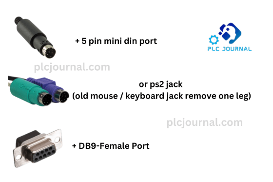
- 5-Pin Mini DIN Port or PS2 Jack. You can obtain this from an old computer mouse or keyboard by removing one of its legs.
- DB9-Female Port: Serves as the link to connect your Panasonic PLC with a contemporary computer.
Now that you have your materials ready, let’s dive into the steps to create your own Panasonic PLC cable.
Step
1: Preparing the Connectors – Panasonic DIY-Cable
Start by taking the 5-Pin Mini DIN Port or PS2 Jack. make sure it’s clean and free from any debris. This connector will be used to interface with your Panasonic PLC.
Next, take the DB9-Female Port, which will connect to your computer or any device with a standard RS-232 serial port. Ensure that it’s also clean and in good condition.
2: Pin Connections
Now, let’s begin by establishing the pin connections. Inside the 5-Pin Mini DIN Port or PS2 Jack, you will find five pins. Next, you need to carefully identify each pin and then connect them to the corresponding pins on the DB9-Female Port as follows:
- First, connect Pin 1 (Data Carrier Detect, DCD) of the DB9-Female Port to Pin 3 (Transmit Data, TXD) of the 5-Pin Mini DIN Port. Additionally, ensure that the connection is secure and properly aligned to prevent any communication errors.
- Next, connect Pin 2 (Receive Data, RXD) of the DB9-Female Port to Pin 2 (Receive Data, RXD) of the 5-Pin Mini DIN Port. Additionally, double-check the alignment to ensure a secure and accurate connection, which will help prevent any communication errors.
- Then, connect Pin 5 (Signal Ground, GND) of the DB9-Female Port to Pin 5 (Signal Ground, GND) of the 5-Pin Mini DIN Port. Additionally, make sure the connection is secure and properly aligned, which will help ensure reliable communication between the devices.
3: Securing the Connections
After making the necessary connections, you should then secure them with soldering or suitable connectors. Furthermore, make sure the wires are properly insulated; otherwise, short circuits may occur. Finally, double-check the connections to ensure everything is safe and reliable.
4: Testing
Before using your homemade cable with your Panasonic PLC, it’s crucial to test. First, it is important to ensure that the connections are correct and that there are no loose wires or shorts. Next, you can do this by connecting the DB9-Female Port to your computer’s RS-232 port and, afterward, connecting the 5-Pin Mini DIN Port to your Panasonic PLC. Then, use the appropriate software or terminal emulation to establish communication with the PLC. Finally, verify that data is being transmitted and received correctly to confirm successful connectivity.
5: Final Assembly
Once you’re satisfied with the cable’s functionality, you can then finalize the assembly by securing the connectors in an enclosure or, alternatively, covering them with heat shrink tubing. Furthermore, this extra step helps prevent any potential damage or interference, ensuring long-term reliability.
Congratulations! You’ve successfully created a Panasonic PLC cable that allows you to connect your older machines to modern devices through an RS-232 interface. This DIY solution not only saves you money but also ensures that you can continue using your legacy equipment without compatibility issues.
In conclusion, as technology advances, it’s essential to find innovative solutions to bridge the gap between old and new equipment. Creating your own Panasonic PLC cable is a prime example of how a little DIY expertise can go a long way in keeping your machinery operational and cost-effective. So, don’t let outdated connectors hold you back; take matters into your own hands and adapt your equipment to meet the demands of the modern world.
Technical Guides
What Is a Programmable Logic Controller (PLC)? Full Explanation
What is HMI? Human-Machine Interface (HMI)-Full Explanation
What is a Variable Frequency Drive?-It’s complete guidelines
What Is a Servo drive and How Does it Work? It’s complete guidelines
Manual PDF
[PDF] Delta PLC DVP-ES2/EX2/SS2/SA2/SX2/SE&TP Operation Manual Free Download
Delta HMI-DOPSoft User Manual Free Download [PDF]
Cable Making
[DIY-Cable] PLC/HMI-Panasonic Connecting PC
[DIY-Cable] PLC/HMI-Keyence Connecting PC
[DIY-Cable] S7-200 Siemens Connecting PC
[DIY-Cable] Mitsubishi PLC Programming Cable SC-09 for FX-Series
[DIY-Cable] PLC Delta Programming Cable DVPACAB230
[DIY-Cable] PLC OMRON Programing Cable for CJ/CS/CQ-Series
[DIY-Cable] PLC “LS/LG” Programing Cable
[DIY-Cable] PLC “Fatek/Facon” Programing Cable
[DIY-Cable] PLC “Vigor” Programing Cable
[DIY-Cable] HMI “Fuji/Hakko” Programing Cable
[DIY-Cable] “HMI Omron NT-Series” Programing Cable
[DIY-Cable] HMI Keyence “VT3-W4 Series” Cable Connecting To PLC
[PDF] HMI-Weintek Connection PLC Guide


