

Introduction: How Does a PLC Work
Have you ever wondered how machines in factories or industrial processes are automated and controlled? The answer lies in a technology called Programmable Logic Controllers (PLCs). Moreover, PLCs have revolutionized industrial operations by providing efficient, precise, and reliable control over machinery and processes, thereby enhancing productivity and reducing human intervention.
In this article, we will dive deep into the inner workings of PLCs to understand how they function and contribute to industrial automation.
What is a PLC and How Does a PLC Work?
PLC stands for Programmable Logic Controller, a specialized computer system designed for industrial automation. PLCs rugged and reliable devices, often used to control machinery, processes, and production lines in diverse industries such as manufacturing, oil and gas, automotive, and more.
Components of a PLC System
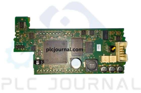
A PLC system comprises several key components that work together seamlessly. Furthermore, understanding these components is essential for designing, troubleshooting, and optimizing PLC-based automation systems. These components include:
1. PLC Processor: The brain of a PLC, responsible for executing instructions and controlling the overall operation.
2. Input/Output Modules (I/O Modules): These modules serve as the interface between the PLC and external devices such as sensors, switches, and other process variables. They receive signals from input devices and send commands to output devices.
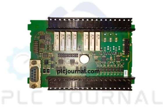
3. Memory: PLCs include various types of memory to store programs, data, and other essential information. Specifically, Read-Only Memory (ROM) is used to store the operating system and input/output configurations, while Random-Access Memory (RAM) holds programs and operational data. Additionally, understanding these memory types is crucial for ensuring efficient program execution and reliable system performance.
4. Power Supply: PLCs require a stable and consistent power supply to ensure uninterrupted operation. Moreover, a reliable power source guarantees that both the PLC and its connected devices function optimally, thereby preventing unexpected downtime and maintaining overall system stability.
Programming a PLC
PLCs can be programmed using a variety of languages, depending on the manufacturer and model. Among these, two of the most commonly used languages are Ladder Logic and Structured Text. Moreover, selecting the appropriate language is essential for ensuring compatibility, efficiency, and ease of program development in industrial automation applications.
1. Ladder Logic: This language mimics traditional relay ladder diagrams and is particularly helpful for those familiar with electrical schematics. It represents logical and decision-making steps through interconnected rungs on a ladder-like interface.
2. Structured Text: Similar to conventional programming languages, Structured Text allows for complex mathematical calculations, data manipulation, and the implementation of advanced control algorithms. Furthermore, it provides greater flexibility and programming possibilities, making it particularly suitable for sophisticated automation tasks and applications that require precise control.
PLC Operation Cycle
The operation of a PLC revolves around a continuous cycle, known as the scan cycle. The scan cycle consists of the following steps:
1. Input Scan: During this phase, the PLC reads and updates input values from connected sensors and devices. It collects data about the state of the external environment.
2. Program Execution: In this step, the PLC processes the program logic based on the input signals it receives. Additionally, it executes instructions, evaluates conditions, performs necessary calculations, and consequently determines the appropriate outputs, ensuring that the controlled system operates as intended.
3. Output Scan: Once the program logic executed, the PLC updates the output values accordingly. These values sent to connected actuators, relays, motors, and other devices to control the desired operations.
4. Housekeeping: The PLC performs various housekeeping tasks during this phase, including updating internal variables, checking for errors, and monitoring system health. It prepares itself for the next scan cycle.
Advantages of PLCs
PLCs offer numerous significant advantages in industrial automation, which make them the preferred choice for controlling machinery and processes. Moreover, their versatility, reliability, and efficiency contribute to improved productivity and streamlined operations. Some key advantages include:
- Flexibility: PLCs can be easily reprogrammed or modified to adapt to changing production requirements. Furthermore, this flexibility enables manufacturers to enhance productivity, respond quickly to market demands, and implement process improvements with minimal downtime.
2. Reliability: PLCs are built to withstand harsh industrial environments, ensuring consistent and reliable operation even under extreme conditions. Moreover, they are designed with redundancy features, fault detection mechanisms, and fail-safe systems, which collectively enhance overall system reliability and minimize the risk of unexpected downtime.
3. Ease of Troubleshooting: PLCs have built-in diagnostics capabilities that simplify troubleshooting and maintenance. They can quickly identify faults, errors, or malfunctions, minimizing downtime and optimizing the overall efficiency of the system.
Applications of PLCs
PLCs are utilized in a wide range of applications across various industries. Furthermore, their versatility and reliability make them essential for automating processes, improving efficiency, and ensuring precise control. Here are a few notable applications:
- Industrial Manufacturing: PLCs are extensively used to control assembly lines, conveyors, and robotic systems in manufacturing industries. Moreover, they play a crucial role in enhancing productivity, maintaining quality control, and ensuring efficient and streamlined production processes.
2. Power Plant Control: In power plants, PLCs play a crucial role in regulating and controlling various operations, including power distribution, load balancing, generator control, and fault detection.
3. Automotive Industry: PLCs utilised in automobile manufacturing for tasks such as controlling robotic arms, ensuring precise assembly, and monitoring quality control systems.
How Does a PLC Work Step by Step?
1. Understanding the Basics of a PLC:
A PLC is a specialized computerized device designed to automate processes by monitoring inputs, executing logical control functions, and generating corresponding outputs. Furthermore, it acts as the central “brain” behind machinery and systems, enabling businesses to streamline operations, improve efficiency, and significantly enhance overall productivity.
2. Input Devices:
The first step in understanding how a PLC works is to comprehend the various input devices it is connected to. These devices can include sensors, switches, buttons, and many others. Moreover, recognizing the role of each input device is essential for accurately monitoring system conditions and ensuring that the PLC responds appropriately to different signals. They provide data to the PLC, which then processed to make decisions and trigger appropriate actions.
3. Processing Unit:
A critical component of a PLC is its processing unit, comprising a microprocessor or a microcontroller. This unit receives inputs from the connected devices, processes the information, and executes the programmed instructions accordingly. These instructions often include logical operations, arithmetic calculations, and decision-making algorithms.
4. Programming Language:
PLCs use specific programming languages, such as ladder logic or structured text, to develop the control program. Ladder logic, resembling electrical circuit diagrams, the most widely used language due to its simplicity and ease of understanding. It enables engineers and technicians to create intuitive programs by using familiar relay and contact logic.
5. Memory:
A PLC operates based on a stored program, which is kept in its memory. Furthermore, this program contains the control logic, instructions, and data that govern the operations of the connected machines or systems, thereby ensuring accurate and automated process control. PLCs typically feature non-volatile memory, ensuring that the program remains intact even during power outages or system restarts.
6. Output Devices:
After processing the inputs and executing the programmed instructions, the PLC generates outputs to control external devices. Furthermore, these output devices can include solenoids, actuators, motor drives, pumps, or other equipment required to perform specific actions or manipulate processes, thereby ensuring accurate and coordinated system operation. Moreover, the PLC sends signals to these output devices based on the logical decisions determined by the programmed control logic, thereby ensuring precise and coordinated operation of the entire system.
7. Communication and Networking:
Today’s PLCs often feature advanced communication capabilities that facilitate seamless integration with other devices and systems. For instance, they can connect to Supervisory Control and Data Acquisition (SCADA) systems, Human Machine Interfaces (HMIs), and other controllers. Additionally, their networking capabilities enable real-time monitoring, remote control, and efficient data exchange, thereby enhancing system scalability, operational efficiency, and overall process management.
8. System Redundancy:
To ensure maximum reliability and minimal downtime, some industrial applications require PLC systems with redundant components. Redundancy involves duplicating critical components, such as power supplies, processors, and communication modules, allowing for automatic failover in case of a component failure. This helps maintain continuous operation and reduce the risk of system failures.
9. Diagnostic and Troubleshooting Tools:
PLCs come equipped with built-in diagnostic and troubleshooting tools, which enable engineers to identify and rectify faults efficiently. Moreover, these tools, accessible through software interfaces, allow for monitoring of inputs and outputs, analysis of program execution, and detection of any anomalies, thereby ensuring smooth and reliable system operation. Real-time data and error logs aid in minimizing downtime during maintenance or troubleshooting procedures.
10. Safety Considerations:
In safety-critical applications, PLCs incorporate specialized safety features such as redundant inputs, fail-safe relays, and emergency stop circuits. Moreover, these features prioritize the protection of personnel, equipment, and the environment. Additionally, PLCs designed with extensive safety functions comply with international safety standards and regulations, thereby ensuring optimal control while enhancing overall safety measures.
How Does PLC Software Work?
PLC software serves as the brain of a PLC system. It is specifically designed to create, program, and execute logical instructions that control the behavior of connected equipment and machinery. Moreover, the software allows engineers and operators to define desired operations and automate tasks efficiently. In addition, the programmability of PLC software provides flexibility for adjusting processes, reducing errors, and ultimately enhancing overall productivity.
Key Components of PLC Software:
1. Programming Environment:
PLC software provides a programming environment where engineers can develop, edit, and test their logic programs. It often includes a user-friendly interface with various programming languages such as ladder logic, function block diagram (FBD), structured text (ST), and more. The choice of programming language depends on the complexity of the task and the familiarity of the programmer.
2. Data Management:
PLC software allows for efficient data management, including variables, tags, and input/output (I/O) devices. Engineers can define variables and assign them to relays, timers, counters, and other logical elements within the PLC program. Moreover, the software ensures seamless communication between these components, facilitating real-time data exchange, monitoring, and analysis, which ultimately enhances system performance and reliability.
3. HMI Integration:
Human Machine Interface (HMI) integration is a critical component of PLC software. Moreover, it enables operators to interact with the system through graphical interfaces, touchscreen panels, or even mobile devices. Through the HMI, operators can monitor the system’s status, troubleshoot issues, and make necessary adjustments in real time. Additionally, PLC software provides tools for designing and customizing the HMI interface to meet specific operational requirements and enhance overall usability.
4. Communication Protocols:
PLC systems often need to interact with other devices, such as sensors, actuators, or supervisory control and data acquisition (SCADA) systems. PLC software supports a variety of communication protocols, including Modbus, Ethernet/IP, Profibus, and others, thereby ensuring seamless data exchange and interoperability between different system components. Moreover, these communication capabilities enable real-time monitoring, remote control, and integration with SCADA and HMI systems, enhancing overall operational efficiency.
Working of PLC Software:
1. Program Development:
Engineers use the programming environment provided by the PLC software to develop a logical program. Furthermore, they define the desired behavior using the chosen programming language, incorporating functions, conditions, and loops to create a comprehensive and efficient control sequence that accurately governs the operation of the connected machinery. The software allows offline programming and simulation, ensuring accuracy and minimizing downtime during the implementation process.
2. Program Transfer:
Once the logical program is developed, it needs to be transferred to the actual PLC hardware for execution. Moreover, PLC software provides features to upload and download logic programs to and from PLCs, thereby establishing a seamless connection between the software and hardware and ensuring accurate implementation of the control logic. This transfer can done via various mediums, such as USB, Ethernet, or serial communication.
3. Execution and Monitoring:
After the logical program is transferred, the PLC software oversees its execution within the connected PLC. Moreover, it continuously monitors inputs and outputs, executing instructions according to predefined logic conditions. In addition, the software enables real-time data analysis and facilitates troubleshooting by displaying system status, error messages, and diagnostic information through the HMI interface, thereby ensuring efficient and reliable operation.
Benefits of PLC Software:
1. Flexibility and Adaptability:
PLC software provides the flexibility to modify and adapt control sequences without requiring physical changes to the system. Furthermore, engineers can easily make adjustments, add new functionalities, or change parameters through programming, thereby allowing processes to evolve efficiently in response to changing operational requirements.
2. Enhanced Efficiency:
With PLC software, complex processes can streamlined, eliminating manual interventions and reducing human errors. Automation leads to increased efficiency, improved productivity, and enhanced overall system performance.
3. Intelligent Decision Making:
PLC software enables data acquisition and analysis, which supports intelligent, real-time decision-making. Moreover, the software can execute complex algorithms, generate detailed reports, and provide insights based on historical data, thereby contributing to optimized process control, enhanced efficiency, and predictive maintenance.
Conclusion: How Does a PLC Work?
In today’s advanced industrial landscape, Programmable Logic Controllers (PLCs) have become the backbone of automation and control systems. Moreover, with their impressive capabilities, PLCs provide essential control and coordination across a wide range of industrial applications. Therefore, understanding how a PLC works and the benefits it offers is crucial for anyone interested in the fascinating and ever-evolving world of industrial automation.
Technical Guides
What Is a Programmable Logic Controller (PLC)? Full Explanation
What is HMI? Human-Machine Interface (HMI)-Full Explanation
What is a Variable Frequency Drive?-It’s complete guidelines
What Is a Servo drive and How Does it Work? It’s complete guidelines
Manual PDF
[PDF] Delta PLC DVP-ES2/EX2/SS2/SA2/SX2/SE&TP Operation Manual Free Download
Delta HMI-DOPSoft User Manual Free Download [PDF]
Cable Making
[DIY-Cable] PLC/HMI-Panasonic Connecting PC
[DIY-Cable] PLC/HMI-Keyence Connecting PC
[DIY-Cable] S7-200 Siemens Connecting PC
[DIY-Cable] Mitsubishi PLC Programming Cable SC-09 for FX-Series
[DIY-Cable] PLC Delta Programming Cable DVPACAB230
[DIY-Cable] PLC OMRON Programing Cable for CJ/CS/CQ-Series
[DIY-Cable] PLC “LS/LG” Programing Cable
[DIY-Cable] PLC “Fatek/Facon” Programing Cable
[DIY-Cable] PLC “Vigor” Programing Cable
[DIY-Cable] HMI “Fuji/Hakko” Programing Cable
[DIY-Cable] “HMI Omron NT-Series” Programing Cable
[DIY-Cable] HMI Keyence “VT3-W4 Series” Cable Connecting To PLC
[PDF] HMI-Weintek Connection PLC Guide


